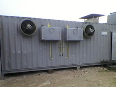
Dynos
in Containers
projects
Specials
Engine Dynos
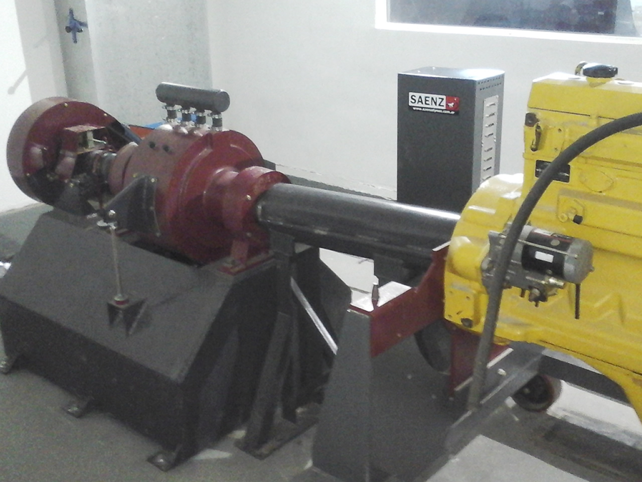
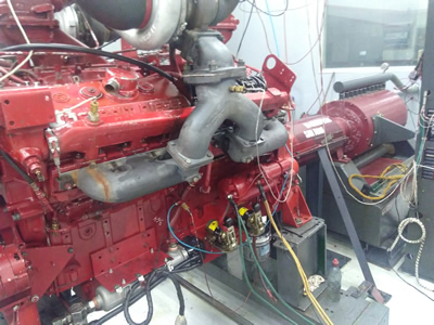
Saenz engine dynos are designed for professional engine testing. Since 1974 we have been manufacturing smooth control, robust, safe and low maintenance hydraulic brakes. Equipped with Smac data acquisition system with automatic control of RPM and motor torque that allows to perform tests with maximum precision, sensitivity and repeatability.
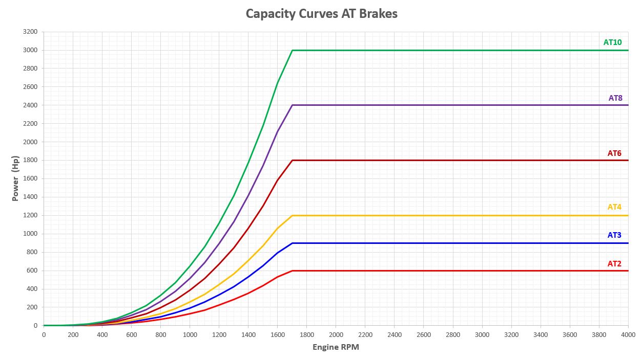
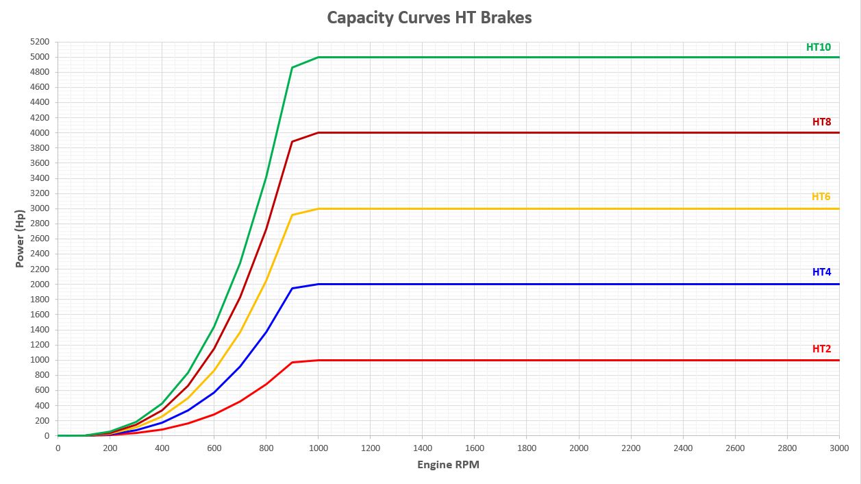
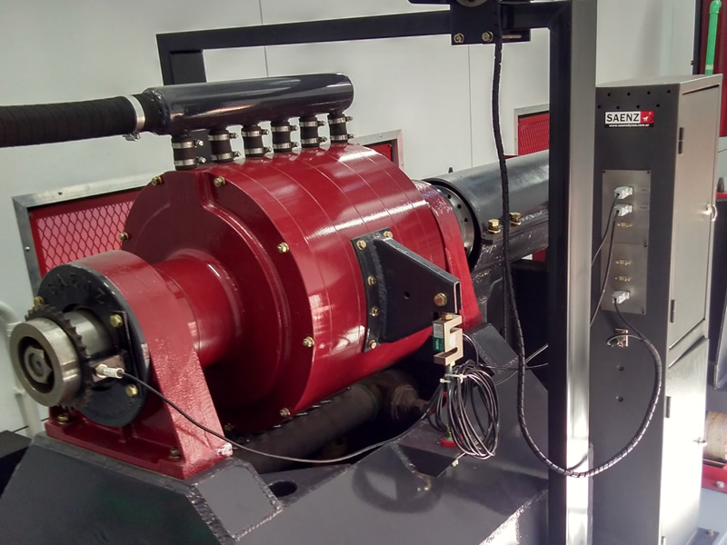
AT | HT
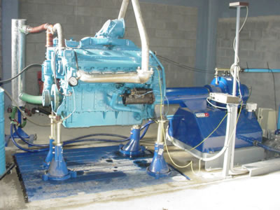
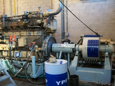
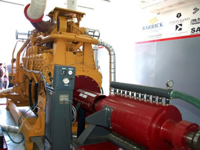
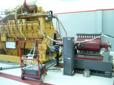
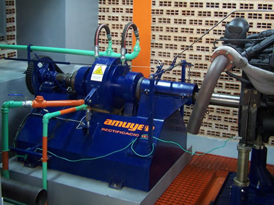
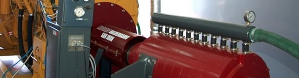
High Torque Engine Dynos
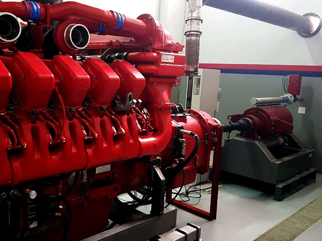
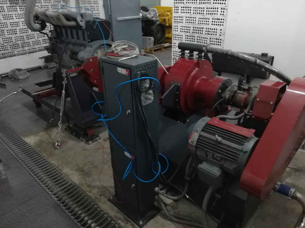
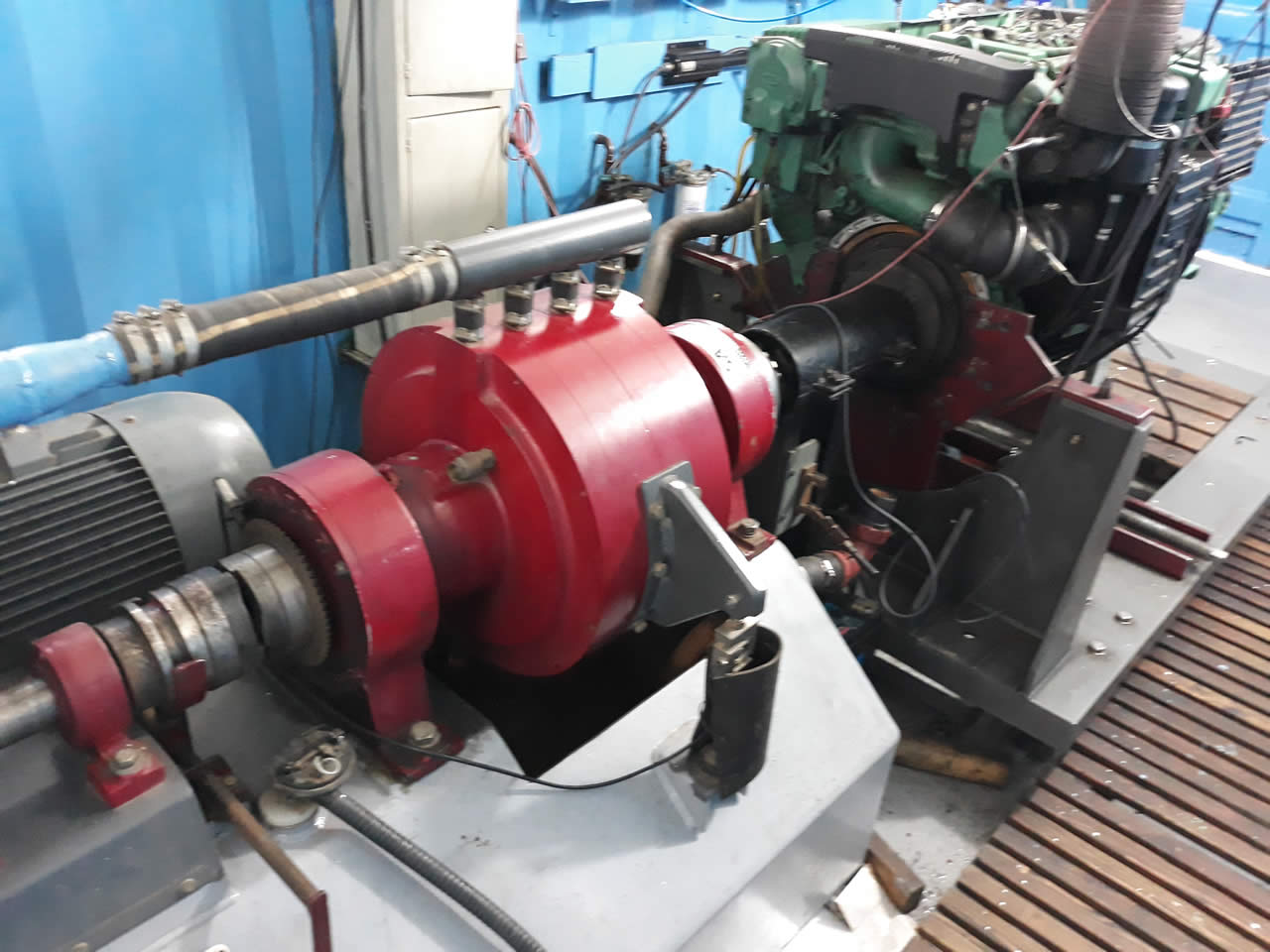
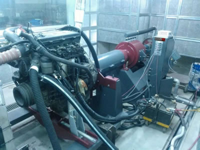
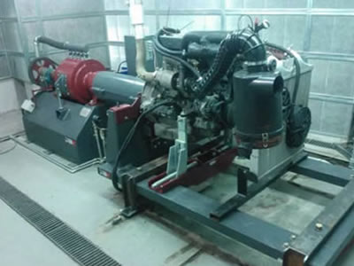
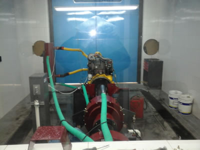
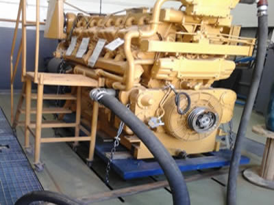
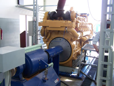
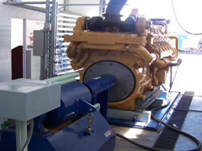
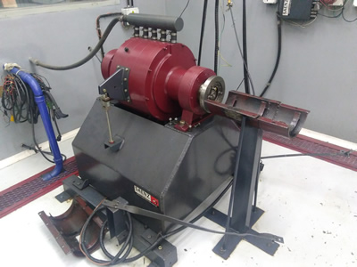
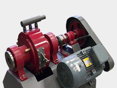
AT and HT dynamometers are the ideal tool to verify and certify a service or overhaul on high torque motors.
Designed for long-term tests handling high power, keeping stable conditions at different levels of motor load to obtain an accurate measurements. AT and HT dynamometer has an integral automatic control system that maintains the variables of rpm, torque and engine temperature according to programmed values for the time required. Dyno software allow to perform test programs with different periods under different power and RPM conditions.

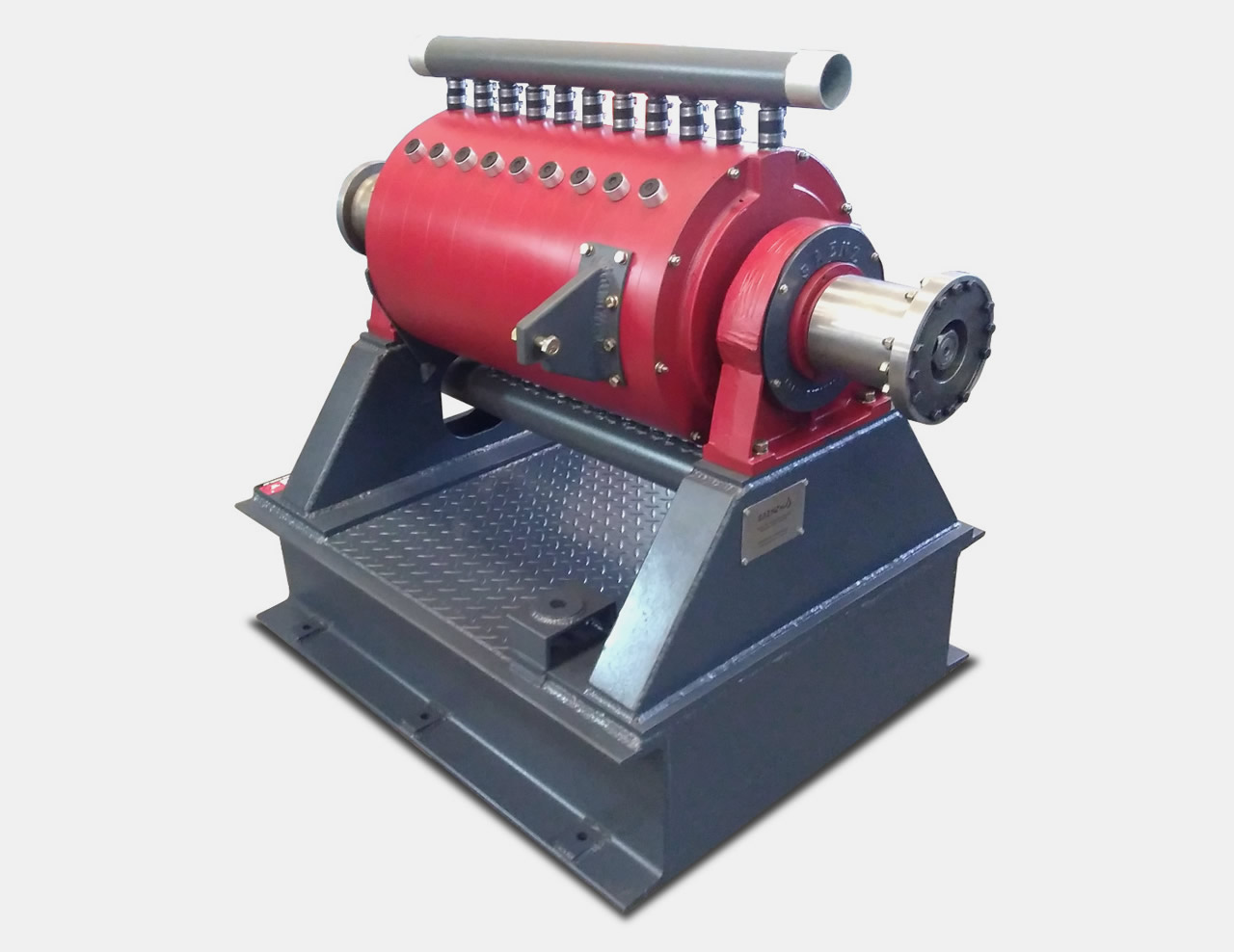
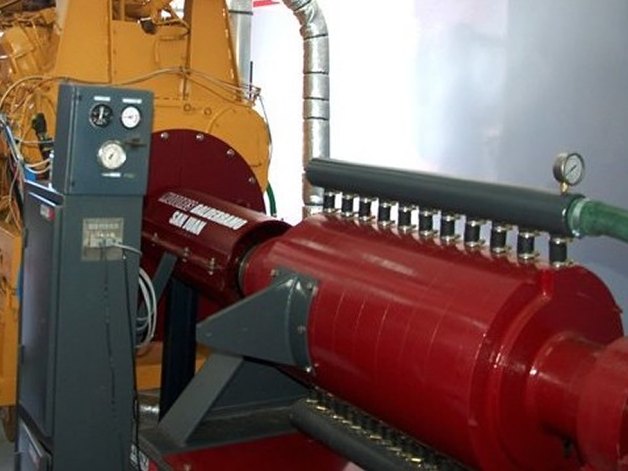
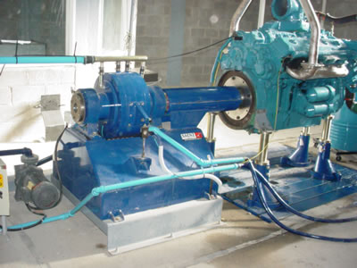
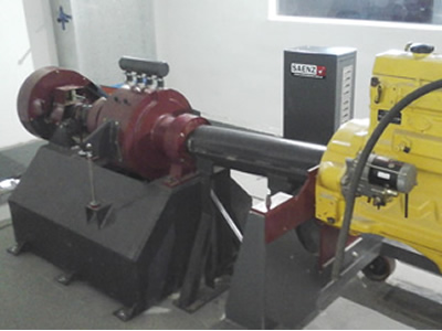
AT and HT brakes have a large rotor diameter, which gives them very high braking torque with total stability and very effective heat dissipation. This makes them robust brakes with low maintenance and life time of more than 30 years.
ACCESORIES
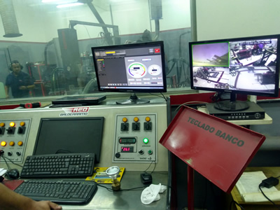
Data acquisition system (SMAC)
Data acquisition system for AT and HT dynamometers has an integral control system that automatically regulates engine torque and rpm to develop the required test programs. The system also controls the engine and aftercooler temperature. The equipment is modular, this means that the sensors and controllers required can be added to measure all the variables desired.

Software is friendly with a large number of tools for the visualization, analysis of results and with specific programs for testing diesel engines. Power curves and all variables are measured and displayed in real time during tests. Results can be compared on flexible charts where all measured parameters and the number of different tests required can be seen. It is also possible to build comparative tables and test reports.
Auxiliar Sensors
Weather Station: reads the temperature, moisture and pressure conditions in the test cell. The software calculates with this information the correction factor for torque and power of the engine.
Water Temperature
Oil Temperature
Exhaust Temperature
Fuel Pressure
Oil Pressure
Lambda readings
Air Consumption
Fuel Consumption
Blow by
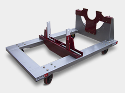
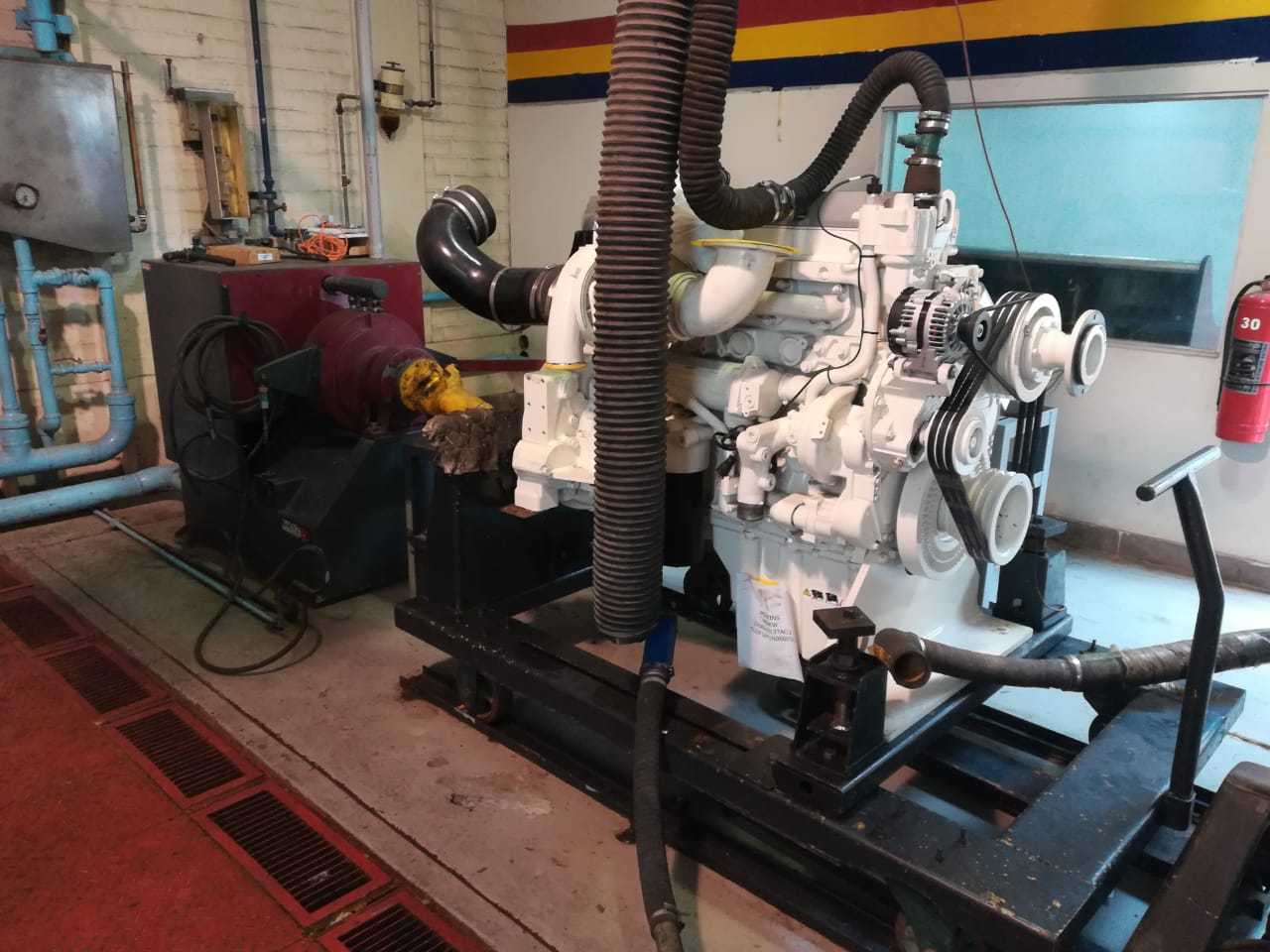
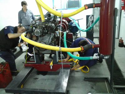
Wheeled Universal engine Docking frame
Mobile frame allows the engine to be mounted outside the test room and easily transported and attached to the dynamometer. Different sizes are available: for 2000, 3000, 5000 and up to 15000kg engines. All the bases have SAE Engine Flywheel Housing to mount the engines: #6, #5, #4, #3, #2, #1, #1/2, #0 and #00.

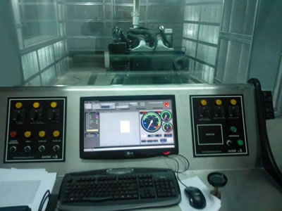
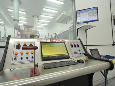
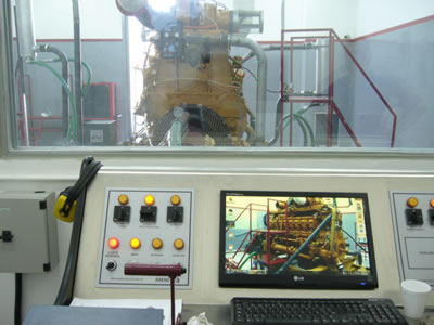
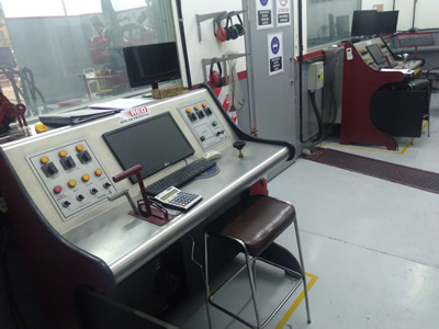
Control and Command Desk
Stainless steel board, contains all the dynos commands, throttle body actuator and brake torque control. With a 24” led TV where the dyno software is displayed.
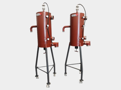
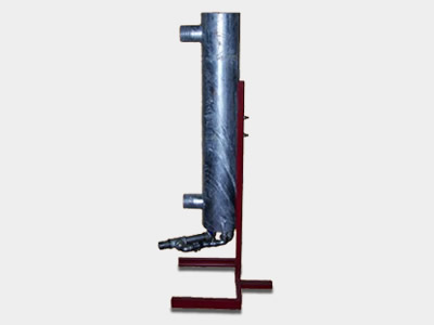
Cooling Column
- Allows to regulate the engine temperature and maintain stable conditions to achieve repetitive measurements.
- Engine water circuit pressure adjustment system.
- Includes a sight glass for detecting leaks
- Analog pressure and temperature clocks for quick check inside the dyno room
- Mobile base
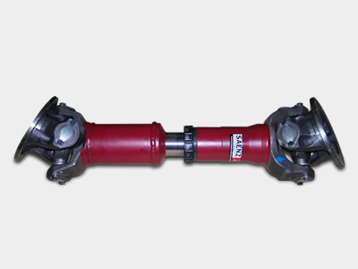
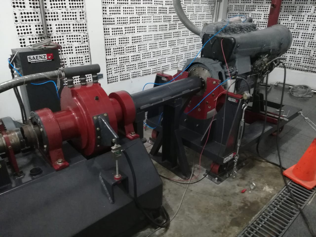
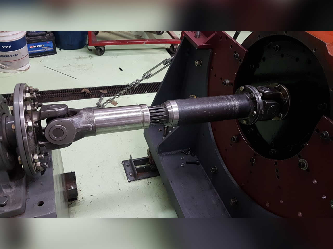
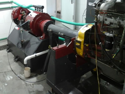
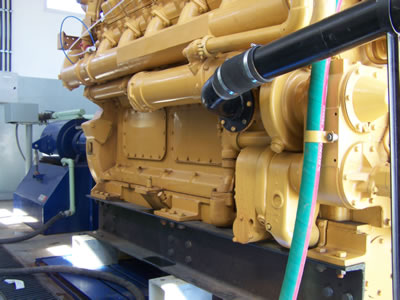
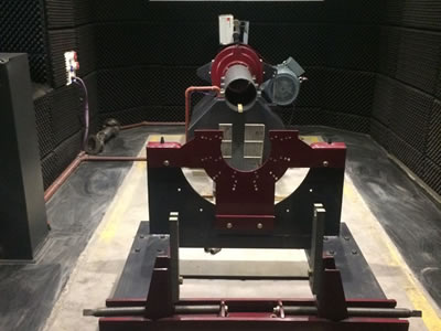
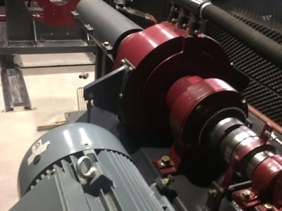
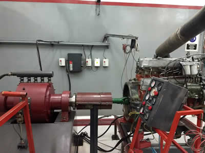
Drive shaft
The dribve shaft allows to couple an large variety of engines to the dyno brake. This type of coupling allows misalignment between the motor and the dynamometer. The shaft is mounted inside a protector that contains it in the event of a failure or eventual failure, minimizing risk for people and the rest of the equipment of the dynamometer.
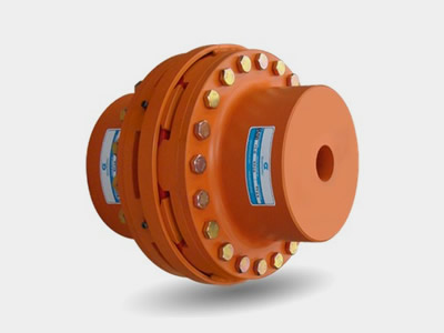
Resilient Couplings
The resilient coupling reduces the transmission of high amplitude torsional vibrations during testing. Helps protect and extend the life of the drive shaft.
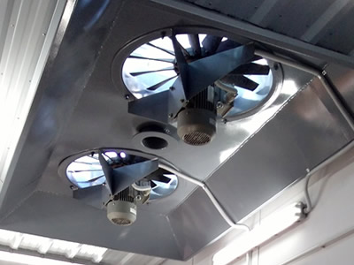
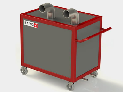
Dyno room ventilation Systems
There are different criteria to define the ventilation system in an engine room. A widely used system is the exhaust hood. Made of steel, the size and amount of fans are defined according to the tested engines.
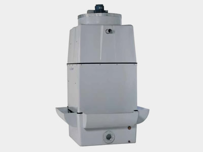
Cooling Tower
Cooling towers extract heat from the dynamometer water circuit generated by the delivered mechanical power and engine cooling systems. The heat is transferred from the water in the circuit to the air, the size of the cooling tower depends on the power of the engines to be tested and is calculated for the maximum capacity of the dynamometer brake.
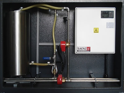
Fuel Consumption System
Fuel consumption is a very important issue of high torque Diesel engines performance and is highly required in repair or overhaul reports. The system works in a serial connection between the main fuel tank (s) and the engine. It has an intermediate tank and two circuits, one for the motor supply and the other for the fuel return circuit. Measurement is gravimetric and is automatically controlled by the system during tests.
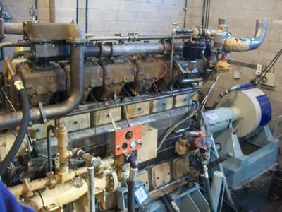
Starter System
The system eliminate the need for batteries, cables and chargers to run the engines starter. Also, it is frequent that some engines are mounted on the dynamometer without its own starting system. The dyno starter allows to start the engines by just pushing a button. For engines up to 1000hp the system includes an electric motor, for larger engines the system includes a pneumatic motor with a crown on the dynamometric brake.
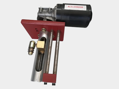
Throttle Actuator
The throttle actuator enables the throttle of mechanical motors to be automated and operated with maximum precision. Actuator stroke and speed are fully adjustable to easily adapt to different devices.
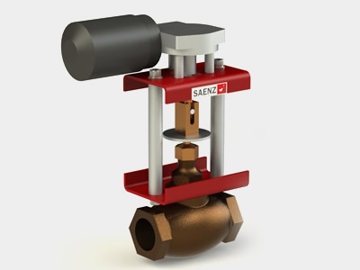
Load Control Valve
Control valve allows remote torque control actuation to prevent the plumbing circuit from passing through the dynamometer command desk. The valve is automatable with the integral automatic control system of AT and HT dynamometers. The valve sizes vary according to the dynamometer model.
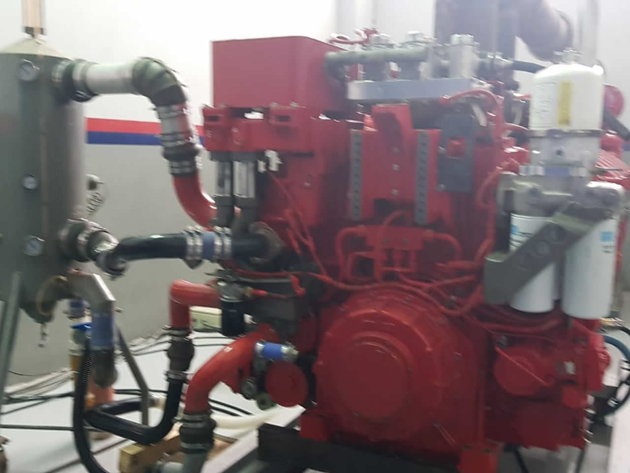
After Cooler simulator
Machinery engines that are disassembled for repair or overhaul frequently do not bring the intercooler system to the dynamometer. This is why the simulator is used to cool the air at the turbo outlet. The system is air- water, with automatic control of air outlet temperature.
Engine aftercooler column
For engines that cool the turbo outlet with a water circuit, a heat exchanger is used to control the temperature of that circuit. The system is automatable and uses fresh water from the general dynamometer circuit.